There are various factors to consider when providing strong wireless LAN coverage in a location, and not every application requires the same type of wireless antenna. In addition, wireless antennas can have a variety of shapes and sizes, each with its specific gain value and intended function.
Radiation Patterns
Antenna gain is measured in decibel-isotropic (dBi) by comparing an antenna to an isotropic antenna. An isotropic antenna is ideal and perfect but impossible to build, so it does not exist. However, it is also the simplest and most basic antenna, making it an excellent starting point for antenna theory.
An isotropic antenna resembles a little circular point. When supplied with alternating current, an RF signal is generated, and electromagnetic waves are emitted in all directions equally. The isotropic antenna generates energy in the form of a continually expanding sphere, and its signal strength remains the same all the way around at a specific distance.
The performance of an antenna may be represented by a sphere with a diameter proportionate to the signal strength. The sphere has a logarithmic scale, and the numbers are presented on the same linear plot. A plot that indicates the relative signal strength around an antenna is called the radiation pattern.
Horizontal and Elevation Planes
A 3D plot is difficult to portray in 2D, especially if the shape is irregular. Most physical antennas aren’t perfect, so their radiation pattern isn’t a perfect sphere. The 3D plot can be divided into two orthogonal planes to show the two perspectives formed from the plot.
The image below shows the sphere divided by two orthogonal planes. The XY plane lies flat along the horizon. It is called the H or horizontal azimuth plane and often gives a top-down perspective of the radiation pattern across the center of the antenna. The XZ plane lies vertically along the sphere’s elevation. It is called the E or elevation plane, giving a side view of the same radiation pattern.
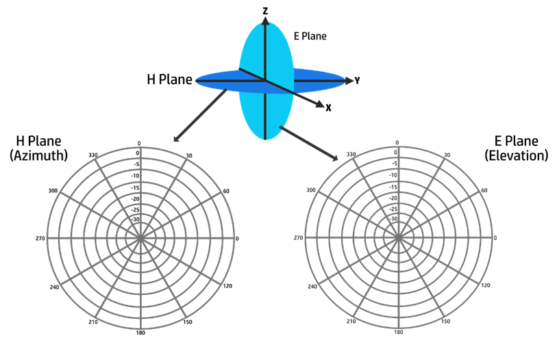
A polar plot can be used to record the outline of every plot. It comprises concentric circles that indicate variations in signal strength recorded at a fixed distance from the antenna. The outermost circle is often used to signify the strongest signal strength, while the inner circles signify lesser signal strength.
Even though the circles are labeled with values such as 0, -5, -10, etc., they may not always indicate absolute dB levels. They are relative measurements to the maximum value at the outside circle. If the maximum is placed on the outermost ring, everything else is lesser than the maximum and lies on the inner rings.
The circles are separated into sectors, allowing for full 360-degree plotting, enabling measurements to be conducted at all angles around the antenna in the plane. When deciding where to install multiple Access Points (APs) in a wireless network, you may need to examine several antenna designs to see whether the antenna is a suitable match for the environment you are attempting to cover with an RF signal.
Antenna Gain
Antennas amplify or add gain to the signal by forming the RF energy as it is propagated into free space. An antenna’s gain measures how effectively it can direct Rf signals in a particular direction.
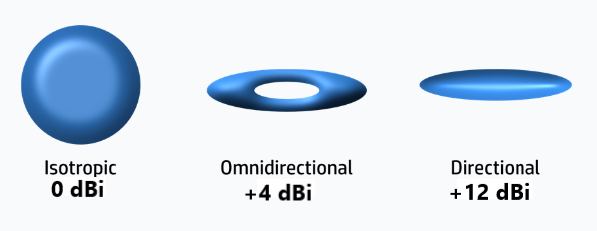
An isotropic antenna radiates RF energy in all directions equally, so it cannot concentrate the RF energy in one direction. The antenna’s gain in dBi is measured in relation to an isotropic antenna. An isotropic antenna’s gain is 10log10(1), or 0 dBi.
The image below shows the isotropic antenna, the omni directional antenna, and the directional antenna radiation patterns and gain values. The gain is lower for omnidirectional antennas, which cover a large area. The gain is higher for directional antennas, which are purposed to cover smaller areas.
Beamwidth
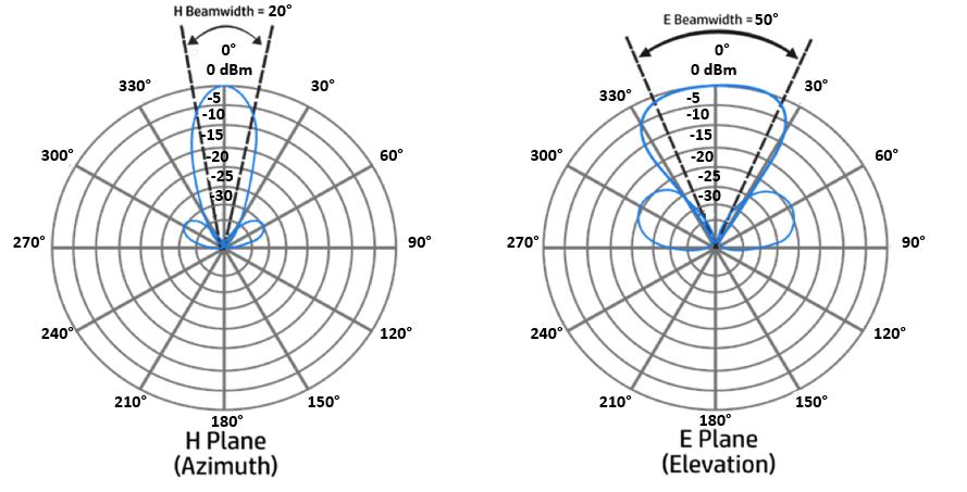
The antenna’s beamwidth measures the antenna’s focus and is usually expressed in degrees. The beamwidth is calculated by finding the plot’s strongest point, typically on the outer ring. The plot is then moved in either direction until the value drops by 3 dB, signifying the point at which the signal is half its maximum power.
Each 3 dB point is intersected by a line from the plot’s center. The angle between the two lines is then determined. For example, the image below shows an H plane beamwidth of 20 degrees and an E plane beamwidth of 50 degrees.
Polarization
An electromagnetic wave is generated when an alternating current is supplied to an antenna. The electromagnetic wave is composed of electrical and magnetic field waves. The electrical component of the wave will always depart from the antenna in a particular orientation.
For example, a vertical wire will emit a wave that oscillates up and down in a vertical direction as it passes through free space. Some WiFi antennas may generate horizontally oscillating waves. Others may generate waves that twist in a 3D spiral motion through free space.
Antenna polarization is the direction of an electrical field wave with regard to the horizon. Vertically polarized antennas generate vertical oscillation, and horizontally polarized antennas generate horizontal oscillation. There is always a magnetic field wave of 90 degrees from the electrical field wave.
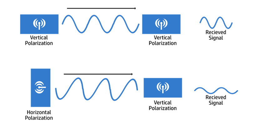
Both the transmitter’s and the receiver’s antenna polarization must match. The received signal might be drastically degraded if the polarization is mismatched.
The image below shows antenna polarization. At the top, both transmitter and receiver use vertical polarization, which optimizes the received signal. However, the bottom pair have mismatched polarization, resulting in poor signal reception.
Download our Free CCNA Study Guide PDF for complete notes on all the CCNA 200-301 exam topics in one book.
We recommend the Cisco CCNA Gold Bootcamp as your main CCNA training course. It’s the highest rated Cisco course online with an average rating of 4.8 from over 30,000 public reviews and is the gold standard in CCNA training: