The RF signal must be strong enough for it to be fully processed. The RF signal strength can be measured in Watts (W) using the amplitude or the signal waveform’s top peak to the bottom peak height. Decibel (dB) conversion is used for exponential values.

Watts (W) and milliWatts (mW) are absolute power measurements, meaning that the amount of energy in the RF signal must be measured accurately. It is quite simple when the measurement is taken at a transmitter’s output since the transmit power level is often known beforehand.
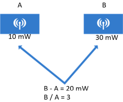
It is often necessary to compare the power levels of different transmitters. For example, transmitter A transmits at 10 mW, and transmitter B transmits at 30 mW. If you subtract the two values (B-A), you can see that B is 20 mW stronger than A. If you divide (B/A), you can see that B is 3 times stronger than A.
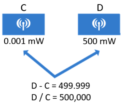
Absolute power measurement values can vary by order of magnitude. In another example below, there are two transmitters, C and D. Subtracting their values would result in 499.999 mW, but with division, D is 500,000 times stronger than transmitter C.
Absolute power values can range from a small decimal to a huge integer number. Therefore, a logarithm function, dB conversion, is used for exponential numbers.
Decibel (dB)
Decibels (dB) indicate power ratios of two values that indicate signal strength, including electrical power and sound pressure. The dB logarithmic unit value can be determined using the following defining equation, where P1 and P2 are absolute power levels from two separate sources:
dB = 10 (log10P2 – log10P1)
P2 represents the source of interest, whereas P1 is referred to as the source of comparison or the reference value. The formula can also be written as:
dB = 10log10(P2/P1)
The power ratio of the two absolute values is computed first, and the result is converted to a logarithmic scale. Both equations provide the same results, but the division formula is more utilized in wireless engineering.
Decibel (dB) Laws
There are three dB laws, which are based on dB changes of 0, 3, and 10:
- Law of Zero – A value of 0 dB indicates that the absolute power values of the source of interest (P2) and the reference value (P1) are the same (P2 = P1). If two power values are the same, the ratio within the logarithm is 1, and log10(1) is zero.
- Law of 3s – A value of 3 dB indicates that the power value of P2 is twice P1, and the ratio inside the logarithm will always be 2, so 10log10(2) = 3 dB. If P2’s power value is half of P1, the result will be -3 dB.
- Law of 10s – A value of 10 dB indicates that the power value of P2 is 10 times that of P1, and the ratio will always be 10, so 10log10(10) = 10 dB. A value of -10 dB indicates that the power value of P2 is one-tenth that of P1. The ratio will be 1/10, and 10log10(1/10) = −10 dB.
When absolute power values multiply, the dB value is positive and could be added. When the power values divide, the dB value is negative and could be subtracted. The table below shows the summarized dB comparisons:

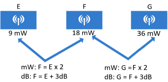
There are three transmitters, E, F, and G, with 9 mW, 18 mW, and 27 mW, respectively. Device F’s value is two times the value of E. Using the dB law of 3s, F will be 3 dB greater than E. So with transmitter G, since it is 2 times the value of F, it will be 3 dB greater than F. To compare E and G, it will be E x 2 x 2 or E + 3 dB + 3 dB. Therefore, G is 6 dB greater than E.
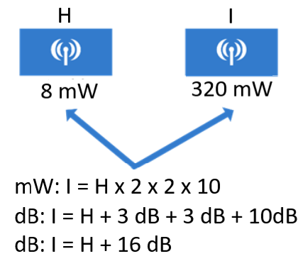
For the next example, we have transmitters H and I. The dB values can be added and subtracted sequentially. Here, H’s value can be multiplied by 2 to get 16, then times 2 again to have 32, and times 10 to get 320 mW. Using dB conversion, it will be H + 3 dB + 3 dB + 10 dB = 16 dB. You can also have H x 10 x 2 x 2 or H x 2 x 10 x 2, which gives 16 dB just the same.
Net Loss
The illustration below shows a transmitter and a receiver, and there will be a net loss along the signal’s path. The signal strength will be reduced at the receiver. Assume that the transmitter’s power output is 500 mW and the arriving signal’s power level at the receiver is 0.00123 mW.
To compare the received and transmitted signal strength, the following formula can be used:
Net Loss = 10log10(received signal strength/transmitted signal strength)
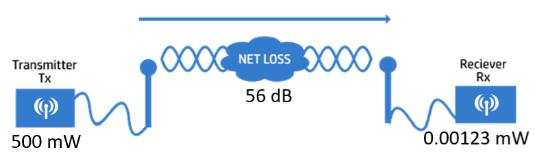
Using the values from the example, the net loss would be 56 dB. To achieve optimum signal strength between the transmitter and the receiver, other transmit power levels can be used or change something about the path.
Net Loss = 10log10(0.00123 mW/500 mW) = -56 dB
Another way is to compare the absolute power along the signal path to a common reference value. The signal power level values will undergo dB conversion. The reference power level in wireless networks is typically 1 mW, so the units are in dBm (dB-milliwatt) logarithmic measure.
To convert the power values to dBm from mW, the following formula is used:
dBm = 10log10(mW)
Using the previous example, the power level values are now converted as follows:
dBm = 10log10(500 mW) = 27 dBm
dBm = 10log10(0.00123 mW) = -29 dBm
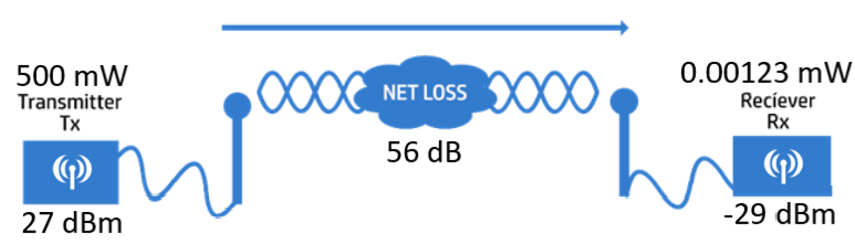
To get the net loss value, add the power level values of the transmitter and the receiver. That will be 27 + 29 = 56 dB net loss, the same result using the previous formula.
Download our Free CCNA Study Guide PDF for complete notes on all the CCNA 200-301 exam topics in one book.
We recommend the Cisco CCNA Gold Bootcamp as your main CCNA training course. It’s the highest rated Cisco course online with an average rating of 4.8 from over 30,000 public reviews and is the gold standard in CCNA training: