Every antenna has a specialized application. We have two commonly used types of antennas, namely, the directional antenna and the omnidirectional antenna. To discern whether a directional or an omnidirectional antenna is to be used, you must first understand the essential functions of both types.
Directional Antenna
Directional antennas focus the RF energy in one direction. As a result, a directional antenna has a higher antenna gain as compared with its omni-directional counterparts. Directional antennas are usually used in elongated interior spaces, such as rooms along a long corridor or warehouse lanes. For outdoor uses, a directional antenna can be used in between distant buildings or on areas out away from a building.
When placed against a ceiling and directed downward, the directional antenna may cover a tiny floor space, reducing an AP’s cell size. As the antenna gain of the directional antenna increases, the coverage distance also increases. However, the angular coverage decreases. This may help to mitigate interference signals and multipath interference, leading to more ordered and comprehensive coverage.
Patch Antenna
A patch antenna is a type of directional antenna that features a flat rectangular design, allowing it to be affixed to a wall or ceiling. Patch antennas have an egg-shaped pattern that stretches away from the flat patch surface, as seen in the figure below. Patch antennas usually have about 6 to 8 dBi gain in the 2.4 GHz band and 7 to 10 dBi gain at 5 GHz.
Yagi-Uda Antenna
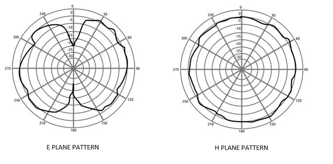
The Yagi-Uda, more commonly referred to as the Yagi antenna, is another directional antenna. Its outer case is cylindrical. However, the antenna really consists of various parallel sections of increasing length. A typical Yagi antenna’s E and H radiation pattern plots are shown below. You can see that the pattern is egg-shaped, and it extends out along the antenna’s length. Yagi antennas have about 10 to 14 dBi antenna gain.
Dish Antenna
Highly directional antennas are designed to carry over the RF signal over very long communications distances in a line-of-sight wireless channel using a narrow beam. These antennas concentrate the RF energy across a single thin elliptical pattern since the target consists of only one receiver site in a particular direction. Therefore, this antenna design does not cover any area beyond the line of sight.
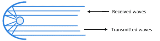
Dish antennas concentrate received signals onto the mounted antenna at the center using a parabolic dish. The parabolic dish reflects the received waves that enter the line of sight onto the center antenna element facing the dish. On the other hand, the transmitted waves from the antenna are focused on the dish, then reflected away from the dish along the line of sight.
The dish antenna’s radiation patterns in the E and H planes are long and narrow, extending away from the dish. The concentrated pattern gives the highest antenna gain of all the wireless LAN antennas, between 20 to 30 dBi.
Omnidirectional Antenna
Omnidirectional antennas or omni antennas are often formed in the shape of a thin cylinder. It sends the signal away from the cylinder in all directions except along the cylinder’s length. Omni-directional antennas provide wide-area coverage since they distribute the RF energy throughout a broad area. However, it also results in a relatively low gain.
An omni-directional antenna emits and absorbs RF energy in equal amounts. Therefore, it results in a 360-degree radiation pattern that allows communication in all directions horizontally. Moreover, the omni-directional antenna polarization is usually vertical, thus, resulting in a donut-shaped isotropic antenna pattern extending further in the H plane than in the E plane.
Dipole Antenna
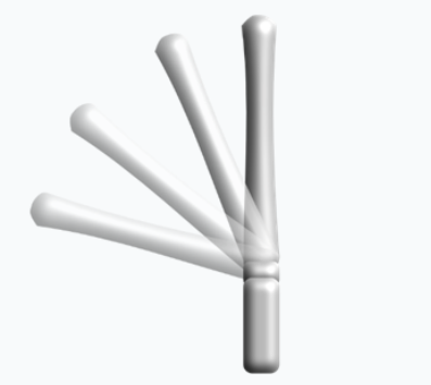
A dipole antenna is a common type of omnidirectional antenna. Some dipole models are developed such that they can be folded up or down, depending on the mounting orientation, whereas others are rigid and fixed.
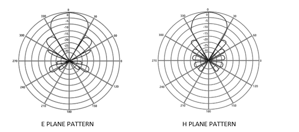
As its name implies, the dipole antenna has two separate wires that radiate an RF signal when an alternating current is applied, as illustrated below. Dipoles typically have an antenna gain of around +2 to +5 dBi.
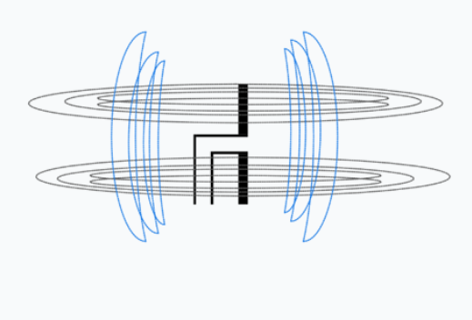
The figure below depicts a conventional dipole antenna’s E and H plane radiation patterns. Consider the dipole lying on its side in the center of the diagram for the E plane. The H plane is looking down on the dipole’s top.
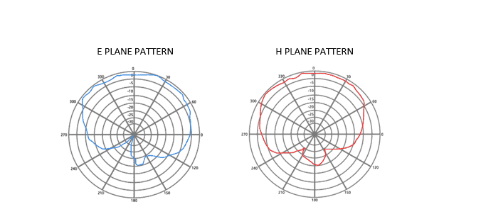
Integrated Omnidirectional Antennas
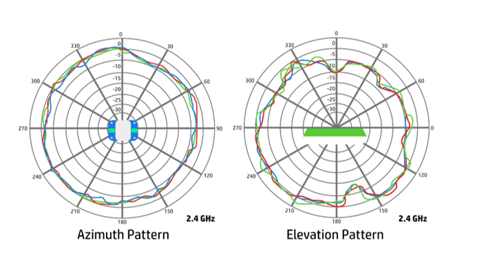
The size of an omnidirectional antenna can be reduced significantly. For example, Cisco Wireless Access Points (APs) can integrate six tiny omni-directional antennas inside a single AP. In the 2.4 GHz band, integrated omnidirectional antennas typically have a gain of 2 dBi, and in the 5 GHz band, it has a gain of 5 dBi. When the E and H planes are merged, the 3D radiation pattern resembles a sphere. The E and H plane radiation patterns for integrated omnidirectional antennas are illustrated below.
Download our Free CCNA Study Guide PDF for complete notes on all the CCNA 200-301 exam topics in one book.
We recommend the Cisco CCNA Gold Bootcamp as your main CCNA training course. It’s the highest rated Cisco course online with an average rating of 4.8 from over 30,000 public reviews and is the gold standard in CCNA training: